JASMINE JOAQUIN

Electralift
THE PROJECT & MY ROLE
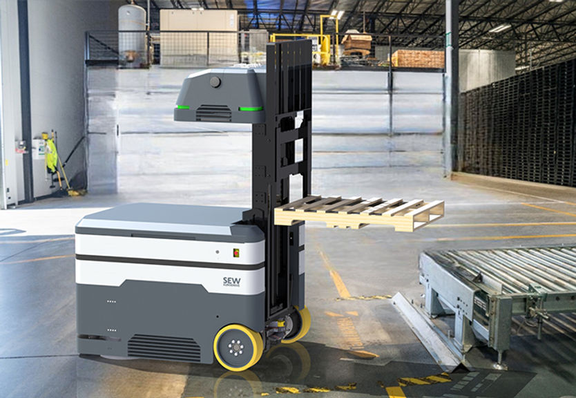
During my four month co-op placement as an Industrial Designer at SEW-EURODRIVE Ltd., I was responsible for designing housings for an automated electric forklift and charger. Working closely with the mechanical and electrical engineers, I used SolidWorks to create the housings and internal support brackets for the forklift and charger. I then generated technical drawings and renderings of them and had the parts manufactured.


RESEARCH
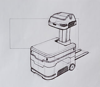
SEW-EURODRIVE's existing automated vehicles were geometrically shaped and primarily grey. I proposed design concepts that kept this design style, and more organic design concepts. The marketing team preferred keeping their existing design language in the new forklift concept, so that is what I continued iterating with.
IDEATION
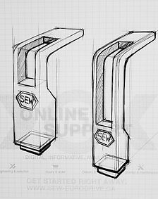
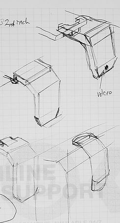
I made quick CAD models and sketches to present different designs to the team. Shown on the left are the concepts that were selected to be developed further in SolidWorks to create the final design.

PROBLEMS & SOLUTIONS
One notable challenge involved changing the manufacturing method for some of the larger parts of the forklift. SEW-EURODRIVE planned to vacuum form the mast cover and base cover of the forklift and received a quote from a vacuum forming company. However, when they went to pay the quoted price, it significantly increased. I immediately looked for a solution. I discovered that no matter where we looked to vacuum form the pieces, it would be a custom order because of the size of the parts. This was why it was expensive. I reached out to several fibreglass moulding companies to see if fibreglass was an affordable manufacturing alternative. We continued with fibreglass moulding and it was more cost-effective and produced more robust parts.
REFINEMENT
The placement of the scanners, the types of scanners used, and many more engineering details, were constantly changing. The final housing design was adjusted as we learned of new constraints.
Additionally, when we ran tests on the above-mounted contact charging unit we discovered that it required 60 pounds of force to be applied to it before it would activate. Our initial charger housing was not strong enough to handle these forces. I had to line the inside of the housing with steel bars to make it more durable.


PROTOTYPING
The final forklift design was prototyped using a combination of sheet metal, fibreglass, and 3D printing (SLS & FDM).
TAKEAWAYS
Through this project, I improved my SolidWorks proficiency. The final forklift assembly had over 1000 parts and the charger had around 700. Each part needed to be modelled and have a technical drawing made for it, and I had to ensure that I did not break relationships between parts while modelling them.